


Analysis of Influencing Factors of Tank Filling Ratio in Liquid Xenon Refueling Process
-
摘要: 液氙在加注过程中可能会出现相变进而降低贮箱的充填率,因此需要了解贮箱充填率的影响因素。采用零维集总参数模型对液氙加注系统进行建模和仿真。基于AMESim计算液氮无排气加注过程中贮箱的充填率,其与文献中的实验结果接近。同时,基于AMESim搭建液氙加注系统,计算不同入口过冷度、入口压强、壁面温度和热流量条件下贮箱的充填率。结果表明,在相同加注时间条件下,提升入口过冷度、增加入口压强可以提升贮箱的充填率,而管路和贮箱受热会降低贮箱的充填率。Abstract: Liquid xenon has low temperature, low latent heat of vaporization and high dynamic viscosity. Due to depressurization or heating, liquid xenon is prone to phase change, forming gas-liquid two-phase flow in the pipeline and the tank, thus reducing the filling ratio of the tank. Therefore, it is necessary to understand the influence factors of the filling ratio of the tank during the refueling process. The zero dimensional lumped parameter model is used to model and simulate the liquid xenon refueling system. Based on AMESim, the filling ratio of the tank in the process of filling liquid nitrogen with no-vent filling is calculated, which is close to the previous experimental results. A liquid xenon refueling system was built based on AMESim, and the filling ratio of the tank was calculated under different inlet subcooling, inlet pressure, pipeline diameter, pipeline wall temperature and tank heat flow. Results show that under the same filling time, increasing the inlet subcooling and the inlet pressure can both improve the filling ratio of the tank, while heating of the pipeline and tank will reduce the filling ratio of the tank.
-
Key words:
- Liquid xenon /
- Refueling /
- Lumped parameter /
- Filling ratio
-
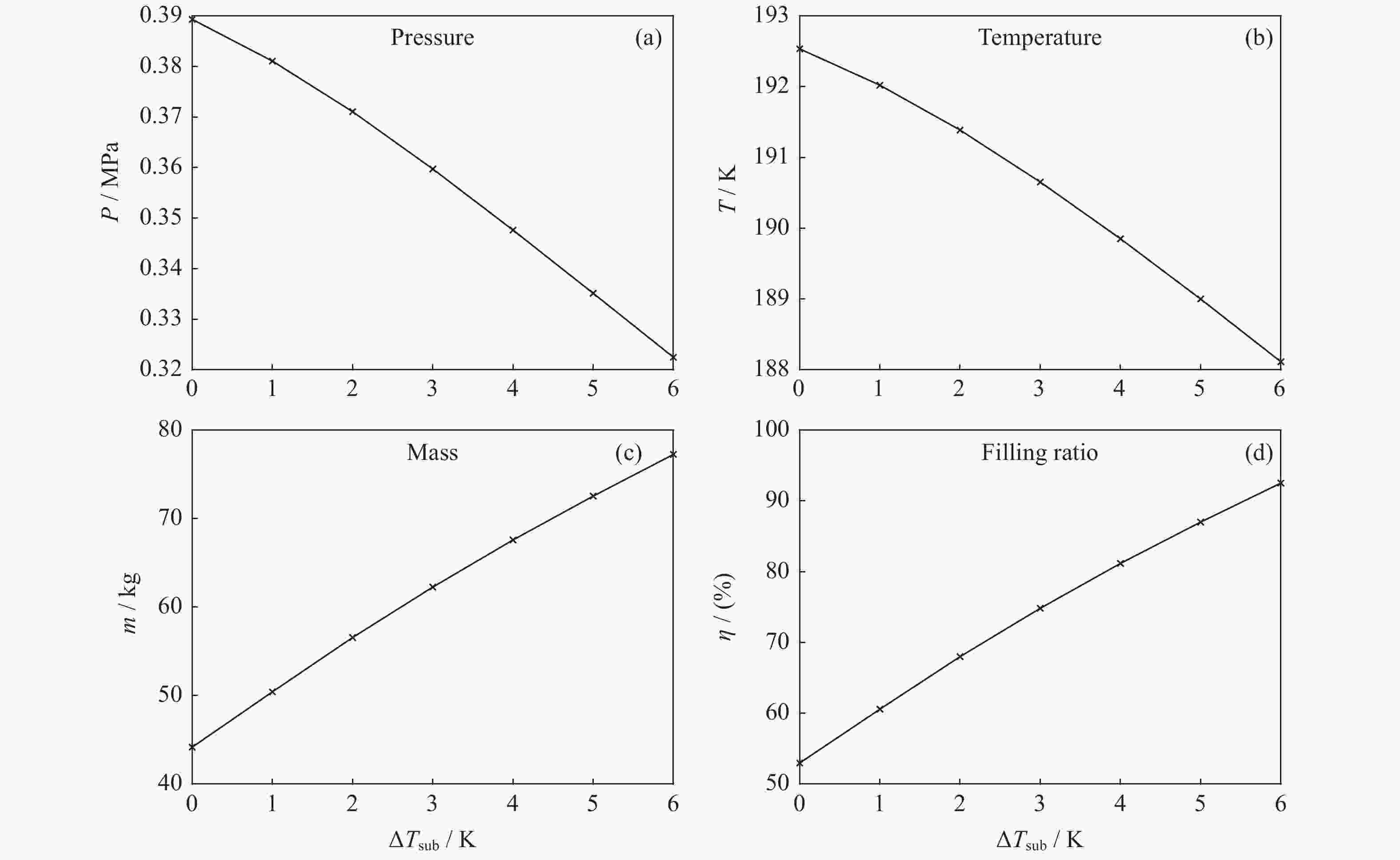
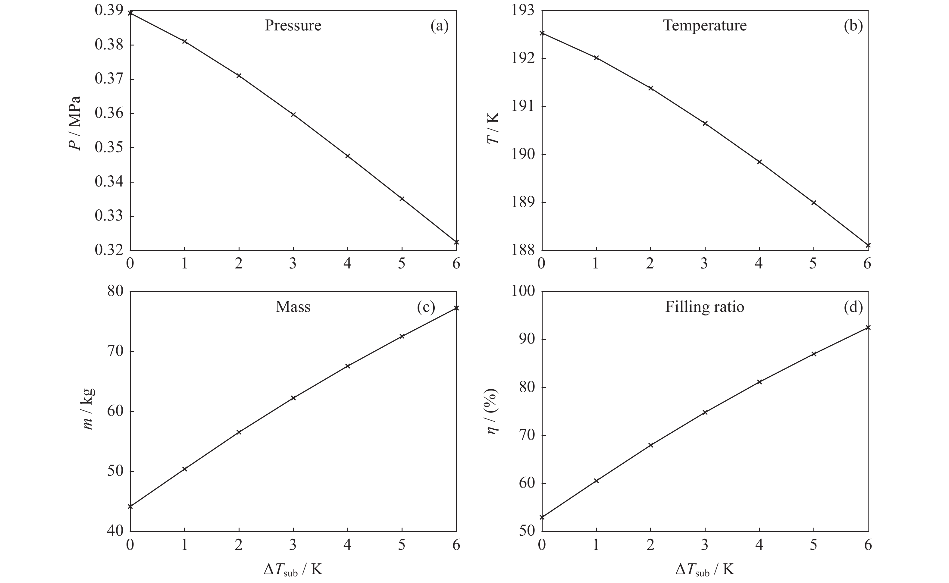
图 4 不同过冷度下被加注贮箱的压强、温度、质量和充填率曲线
Figure 4. Diagrams of pressure, temperature, mass and filling ratio of receiving tanks with different subcooling degrees
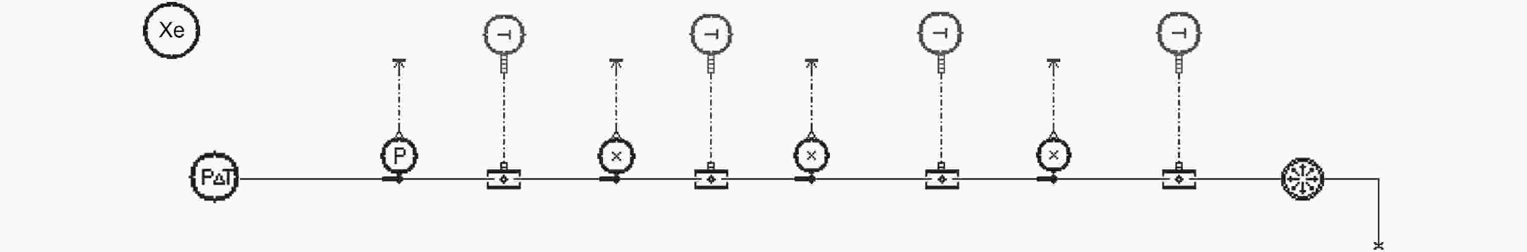
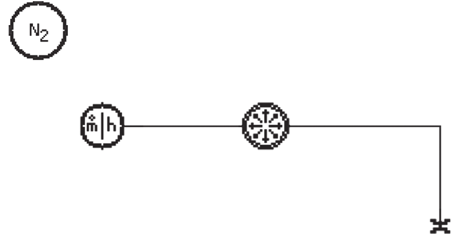
图 5 管壁受热条件下液氙加注系统仿真模型
Figure 5. Refueling system simulation model of liquid xenon under the condition of pipe wall heating
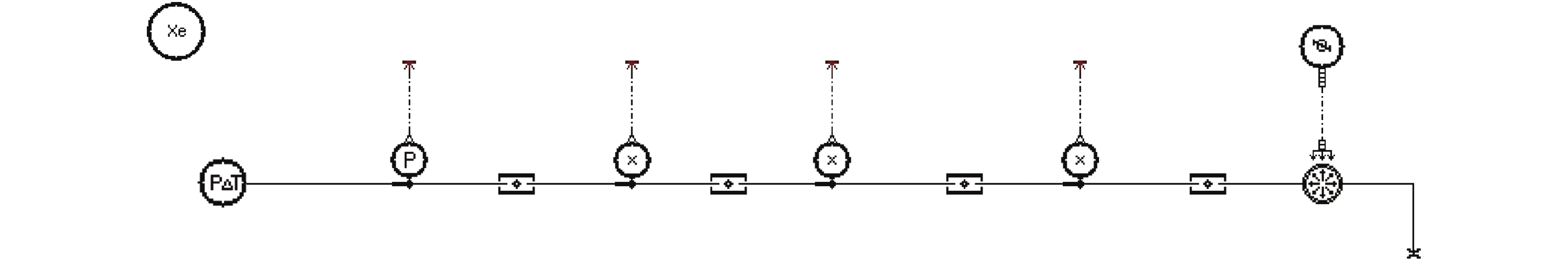
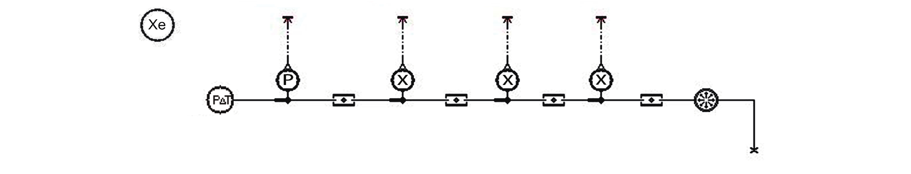
图 6 贮箱受热条件下液氙加注系统仿真模型
Figure 6. Refueling system simulation model of liquid xenon under the condition of tank heating
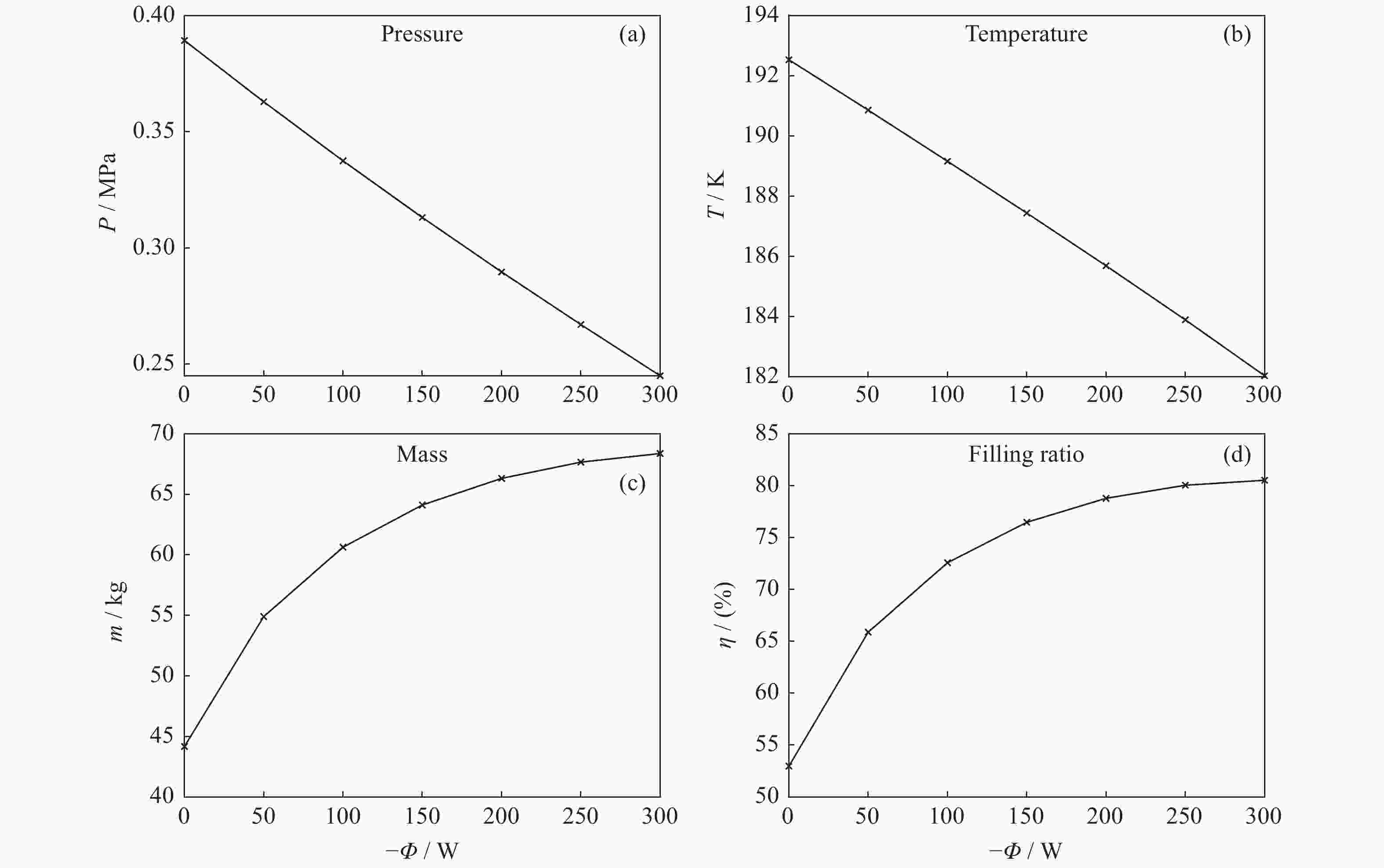
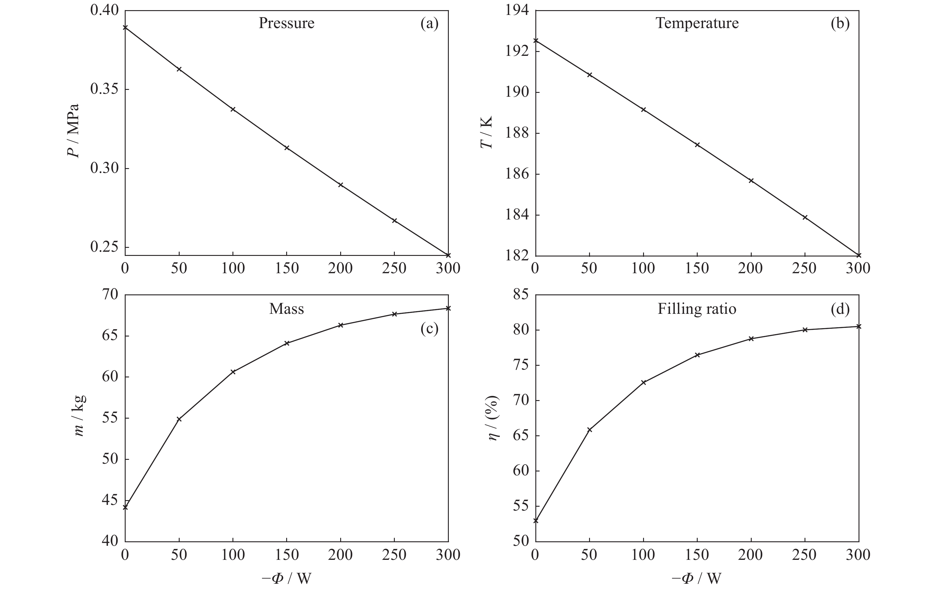
图 7 热流量对贮箱压强、温度、质量和充填率的影响
Figure 7. Influence of the heat flow ratio on the pressure, temperature, mass and filling ratio of the tank
表 1 AMESim中两相流库模型
Table 1. Two-phase flow reservoir in AMESim
模块图标 模块名称 功能 
推进剂 确定工质的物性参数 
恒温恒压源 提供恒定的压强和温度,作为热力学状态确定边界条件 
恒质量和焓流量源 提供恒定的质量流量和比焓,作为热力学状态确定边界条件 
通用传感器 监测管路截面的流量、干度、密度等流动参数 
管路 计算绝热管路的摩擦压降 
贮箱 计算贮箱内的两相流状态 
恒热流量源 给定热流量 
恒温源 给定恒壁温  下载: 导出CSV
表 2 地面液氮无排气加注实验工况
Table 2. No-vent fill experimental conditions of liquid nitrogen
序号 入口温度/K 入口流量/(kg·s–1) 初始温度/K 初始压强/MPa 贮箱体积/L 加注时间/s 1 72.8 0.0597 123.9 0.0248 141.58 1891 2 70.0 0.0809 151.7 0.0269 141.58 1416 3 67.8 0.0847 166.1 0.0310 141.58 1289 4 79.4 0.0537 97.8 0.0338 141.58 1873 5 79.0 0.672 107 0.1 180 184 6 87.9 0.442 110 0.1 180 276 7 81.3 0.190 119 0.1 180 472 8 93.5 0.370 155 0.1 180 311 9 79.1 0.508 123 0.1 180 206
下载: 导出CSV
表 3 贮箱充填率计算值与实验值的比较
Table 3. Comparison of calculated values of the filling ratio with experimental values
序号 实验值/(%) 计算值/(%) 误差/(%) 1 93 96.8 3.8 2 98 96.8 –1.2 3 97 91.2 –5.8 4 90 89.4 –0.6 5 90 86.7 –3.3 6 91.3 90.3 –1.0 7 63.7 63.4 –0.3 8 91 88.3 –2.7 9 73 73.3 0.3
下载: 导出CSV
表 4 不同过冷度下贮箱的充填率
Table 4. Tank filling ratios with different subcooling degrees
入口过冷度/K 压强/MPa 温度/K 质量/kg 干度 充填率/(%) 0 0.3893 192.5 44.17 0.0111 53.0 1 0.3811 192.0 50.42 0.00796 60.6 2 0.3711 191.4 56.57 0.00562 68.0 3 0.3597 190.7 62.26 0.00390 74.8 4 0.3476 189.9 67.59 0.00260 81.2 5 0.3351 189.0 72.55 0.00162 87.0 6 0.3225 188.1 77.26 0.000843 92.5
下载: 导出CSV
表 5 不同入口压强下贮箱的充填率
Table 5. Tank filling ratios under different inlet pressures
入口压强/MPa 压强/MPa 温度/K 质量/kg 干度 充填率/(%) 0.2 0.1736 175.0 38.27 0.00719 44.1 0.3 0.2649 183.7 52.26 0.00534 61.6 0.4 0.3597 190.7 62.26 0.00390 74.8 0.5 0.4575 196.5 69.90 0.00251 85.5 0.6 0.5577 201.6 75.74 0.00113 94.1
下载: 导出CSV
表 6 不同管壁壁面温度下贮箱的充填率
Table 6. Tank filling ratios under different wall temperatures
壁面温度/K 压强/MPa 温度/K 质量/kg 干度 充填率/(%) 170 0.1577 173.1 52.95 0.00332 60.9 180 0.2362 181.3 44.45 0.00706 52.0 190 0.3455 189.7 28.50 0.0217 33.6
下载: 导出CSV
表 7 比较不同热流量情况下贮箱内压强、温度、质量和充填率
Table 7. Pressure, temperature, mass and filling ratio of the tank under different heat fluxes
热流量/W 压强/MPa 温度/K 质量/kg 干度 充填率/(%) 0 0.3893 192.5 44.17 0.0111 53.0 –50 0.3629 190.9 54.90 0.00605 65.9 –100 0.3375 189.2 60.63 0.00412 72.6 –150 0.3131 187.4 64.12 0.00311 76.5 –200 0.2897 185.7 66.31 0.00253 78.8 –250 0.2670 183.9 67.66 0.00216 80.0 –300 0.2450 182.0 68.37 0.00193 80.5
下载: 导出CSV
表 8 不同加热热流量下贮箱的充填率
Table 8. Tank filling ratios under different heating heat fluxes
热流量/W 压强/MPa 温度/K 质量/kg 干度 充填率/(%) 0 0.3893 192.5 44.17 0.0111 53.0 5 0.3921 192.7 42.65 0.0120 52.1 10 0.3948 192.9 40.98 0.0131 49.1 15 0.3976 193.0 39.10 0.0144 46.8
下载: 导出CSV
-
[1] CHATO D J. Thermodynamic modeling of the no-vent fill methodology for transferring cryogens in low gravity[C]//Proceedings of the 24 th Joint Propulsion Conference. Boston: AIAA, 1988 [2] SAUTER D, HOCHSTEIN J, FITE L. Computational modeling of cryogenic propellant resupply[C]//Proceedings of the 44 th AIAA Aerospace Sciences Meeting and Exhibit. Reno: AIAA, 2006 [3] KIM Y, LEE C, PARK J, et al. Experimental investigation on no-vent fill process using tetrafluoromethane (CF4)[J]. Cryogenics, 2016, 74: 123-130 doi: 10.1016/j.cryogenics.2015.12.005 [4] WANG Caili, WANG Rongshun, LI Yang, et al. Comparison of performance about four different filling configurations in no-vent filling process[J]. Cryogenics, 2008(5): 35-39,55 doi: 10.3969/j.issn.1000-6516.2008.05.007 [5] WANG Caili. Modeling and experimental study of no-vent fills for cryogenic liquid[D]. Shanghai: Shanghai Jiao Tong University, 2012 [6] WANG L, LI Y Z, ZHANG F N, et al. Performance analysis of no-vent fill process for liquid hydrogen tank in terrestrial and on-orbit environments[J]. Cryogenics, 2015, 72: 161-171 doi: 10.1016/j.cryogenics.2015.10.001 [7] MA Yuan, WANG Lei, SUN Peijie, et al. Numerical investigation of no-vent fill process of cryogens under microgravity condition[J]. Cryogenics, 2017(4): 7-13,20 doi: 10.3969/j.issn.1000-6516.2017.04.002 [8] MA Y, LI Y Z, ZHU K, et al. Investigation on no-vent filling process of liquid hydrogen tank under microgravity condition[J]. International Journal of Hydrogen Energy, 2017, 42(12): 8264-8277 doi: 10.1016/j.ijhydene.2017.02.198 [9] AMESim User’s Guides[M]. LMS Imagine S. A., 2016 [10] WANG Lei, LI Yanzhong, LI Cui, et al. Numerical comparison of three ullage models for the tank pressurization process of liquid rocket during outflow[J]. Journal of Aerospace Power, 2011, 26(9): 1995-2001 [11] MORAN M E, NYLAND T W, PAPELL S S. Liquid Transfer Cryogenic Test Facility: Initial Hydrogen and Nitrogen No-Vent Fill Data[R]. Washington: NASA, 1990 -
-

 下载:
下载:


计量
- 文章访问数: 987
- HTML全文浏览量: 496
- PDF下载量: 37
-
被引次数:
0(来源:Crossref)
0(来源:其他)

